Ready to onboard?
Are you ready to join DistyParts and
grow your business?


| Distributor | Stock | Pricing | MOQ | PKG | Lead Time | Date Code | On Order Quantity | On Order Delivery | |
|---|---|---|---|---|---|---|---|---|---|
|
90,400 pcs
|
90400 pcs | On Request | 1 | On Request | On Request | On Request | On Request | On Request |
| Category | |
| Manufacturer Name | |
| Configuration | |
| Current | |
| Drain Current Continuous (Maximum @ TA=25 °C, Q 1 (N-Channel) | |
| Drain Current Continuous (Maximum @ TA=25 °C, Q 2 (P-Channel) | |
| Drain Source On Resistance (Typical/Maximum @ VGS=-2.5 V, ID=-3.0 A, Q 2) | |
| Drain Source On Resistance (Typical/Maximum @ VGS=-4.5 V, ID=-3.8 A, Q 2) | |
| Drain Source On Resistance (Typical/Maximum @ VGS=-4.5 V, ID=-3.8 A, TJ=125 °C, Q 2) | |
| Drain Source On Resistance (Typical/Maximum @ VGS=2.5 V, ID=4.2 A, Q 1) | |
| Drain Source On Resistance (Typical/Maximum @ VGS=4.5 V, ID=5.5 A, Q 1) | |
| Drain Source On Resistance (Typical/Maximum @ VGS=4.5 V, ID=5.5 A, TJ=125 °C, Q 1) | |
| Drain to Source Voltage (Vdss) | |
| FET Feature | |
| Gate Charge (Qg) (Max) @ Vgs | |
| Gate Charge (Typical/Maximum @ Vgs=4.5 V) | |
| Gate Threshold Voltage (Minimum/Typical/Maximum @ VDS=VGS, ID=250 µA, Q 1) | |
| Gate Threshold Voltage (Minimum/Typical/Maximum @ VDS=VGS, ID=250 µA, Q 2) | |
| Gate-Source Voltage | |
| Input Capacitance (Ciss) (Max) @ Vds | |
| Input Capacitance (Typical @ VDS=-10 V, f=1 MHz, Q 2) | |
| Input Capacitance (Typical @ VDS=10 V, f=1 MHz, Q 1) | |
| Mounting Type | |
| Operating Temperature | |
| Output Capacitance (Typical @ VDS=-10 V, f=1 MHz, Q 2) | |
| Output Capacitance (Typical @ VDS=10 V, f=1 MHz, Q 1) | |
| Power | |
| Power Dissipation (Maximum @ Note 1 a, Q 1 (N-Channel) | |
| Power Dissipation (Maximum @ Note 1 b, Q 2 (P-Channel) | |
| Rds On (Max) @ Id, Vgs | |
| Reel Size | |
| Reverse Transfer Capacitance (Typical @ VDS=-10 V, f=1 MHz, Q 2) | |
| Reverse Transfer Capacitance (Typical @ VDS=10 V, f=1 MHz, Q 1) | |
| Standard Package Quantity | |
| Supplier Device Package | |
| Tape & Reel | |
| Tape Width | |
| Technology | |
| Thermal Resistance Junction To Ambient (Maximum @ Note 1 a, Q 1) | |
| Thermal Resistance Junction To Ambient (Maximum @ Note 1 b, Q 2) | |
| Turn On Delay Time (Typical/Maximum @ VDD=10 V, ID=... (not specified), Q 1) | |
| Turn On Delay Time (Typical/Maximum @ VDD=10 V, ID=... (not specified), Q 2) | |
| Vgs(th) (Max) @ Id |
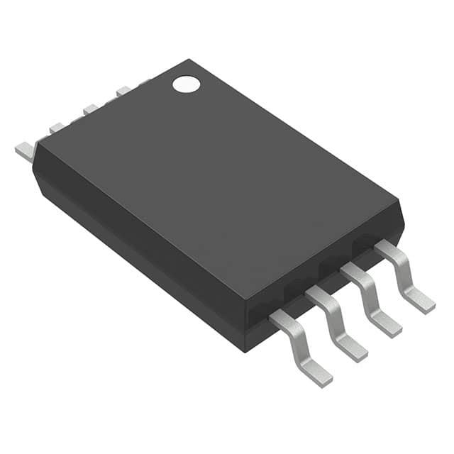
The FDW2521C is a complementary N and P-Channel MOSFET produced using Fairchild Semiconductor's advanced PowerTrench process. This device integrates both an N-Channel and a P-Channel MOSFET in a single 8-TSSOP surface mount package, minimizing board space for applications requiring both polarities. Key specifications include a maximum drain-source voltage of 20V for both channels. The N-Channel (Q1) is rated for 5.5A continuous drain current with a typical on-resistance of 21 mΩ at VGS=4.5V, while the P-Channel (Q2) is rated for -3.8A with a typical on-resistance of 43 mΩ at VGS=-4.5V. Both channels feature logic level gate drive with gate threshold voltages of 0.6-1.5V (N) and -0.6 to -1.5V (P). The device has low gate charge of 17 nC and input capacitance of 1082 pF (N) and 1030 pF (P), enabling efficient switching. The operating junction temperature range is -55°C to 150°C. The FDW2521C is supplied in tape and reel packaging with 2500 units per reel, suitable for automated assembly. Typical applications include DC/DC converters, power management, and load switching.
20 V for both N and P-Channel.
8-TSSOP (0.173", 4.40mm Width).
-55°C to 150°C (junction).
According to existing data, it is marked as RoHS3 Compliant, but this is unverified.
21 mΩ typical at VGS=4.5V, ID=5.5A.
5.5 A for N-Channel (Q1) and -3.8 A for P-Channel (Q2) at TA=25°C.
Yes, the gate threshold voltage is 0.6-1.5V for N-Channel and -0.6 to -1.5V for P-Channel.