

| Distributor | Stock | Pricing | MOQ | PKG | Lead Time | Date Code | On Order Quantity | On Order Delivery | |
|---|---|---|---|---|---|---|---|---|---|
|
564 pcs
|
564 pcs | On Request | 1 | On Request | On Request | On Request | On Request | On Request |
| Category | |
| Manufacturer Name | |
| Turn Off Time | |
| Turn On Time |
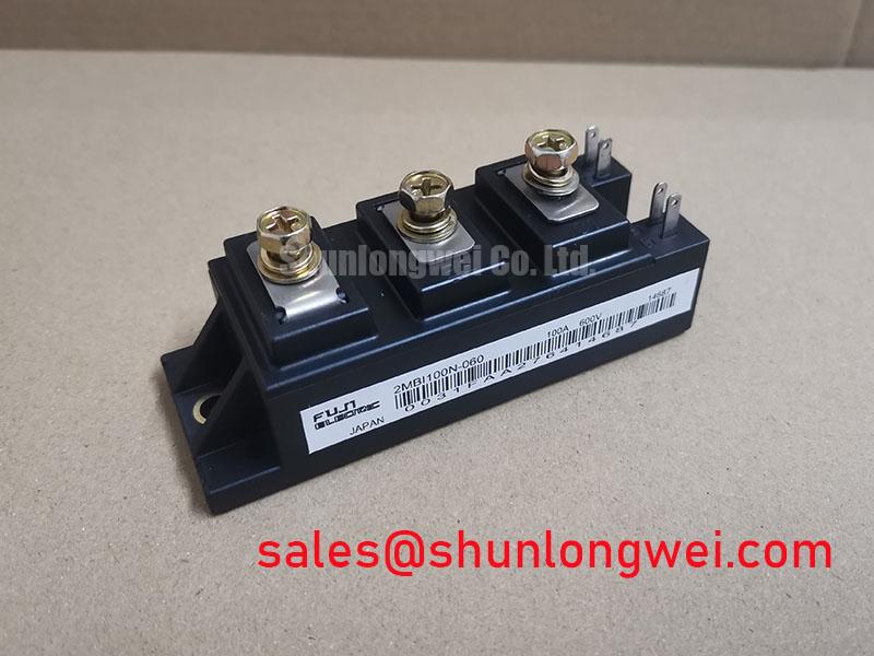
Engineered for high-power switching, the Fuji Electric 2MBI100N-060 IGBT module delivers a robust solution for motor controls and uninterruptible power supplies. This component integrates two N-channel IGBTs in a half-bridge configuration, focusing on reducing total power dissipation and enhancing thermal stability. Key to its performance are a low saturation voltage and optimized switching characteristics, which directly contribute to higher operational efficiency in demanding applications. The module's design also features minimized internal stray inductance, a critical factor for reliable operation at high switching frequencies.
The 2MBI100N-060's performance is anchored by its electrical specifications. A low VCE(sat) directly reduces conduction losses, simplifying thermal management. For systems like variable frequency drives (VFDs), this translates to smaller heatsinks and potentially higher power density. The module’s structure is designed for efficient heat transfer, ensuring that the junction temperature remains within safe operating limits even under heavy loads.
The Fuji Electric 2MBI100N-060 IGBT Module is specified for applications where switching efficiency and reliability are paramount. Its characteristics make it a strong candidate for the power stages of AC and DC motor controllers, servo drives, and uninterruptible power supplies (UPS). In motor drives, the module's fast switching times and low saturation voltage enable precise control and reduce energy consumption. For systems demanding continuous operation, such as industrial welding machines or large-scale UPS installations, its robust thermal performance and square Reverse Bias Safe Operating Area (RBSOA) provide the necessary durability.
Key Specifications: Collector-Emitter Voltage (VCES): 600V Continuous Collector Current (IC): 100A at Tc=80°C Collector-Emitter Saturation Voltage (VCE(sat)): 2.2V (Typ) / 2.8V (Max) Total Power Dissipation (PC): 400W Per IGBT Turn-on Time (ton): 0.6µs (Typ) Turn-off Time (toff): 0.6µs (Typ) Thermal Resistance (Junction to Case) (Rth(j-c)): 0.31 °C/W
| Qty | Low | High |
|---|---|---|
| 1+ | $0.99 | $0.99 |
Estimated market price range - modelled values for guidance only, not live distributor offers.
The maximum Collector-Emitter Voltage (VCES) is 600V at Tj=25°C.
The continuous collector current (IC) is 100A at a case temperature of 80°C.
The typical Collector-Emitter Saturation Voltage (VCE(sat)) is 2.2V when IC=100A, VGE=15V, and Tj=25°C.
The total power dissipation (PC) per IGBT is 400W.
The typical turn-on time (ton) is 0.6µs when IC=100A and VCC=300V.
The typical turn-off time (toff) is 0.6µs when IC=100A and VCC=300V.
The thermal resistance (Junction to Case) (Rth(j-c)) is 0.31 °C/W.